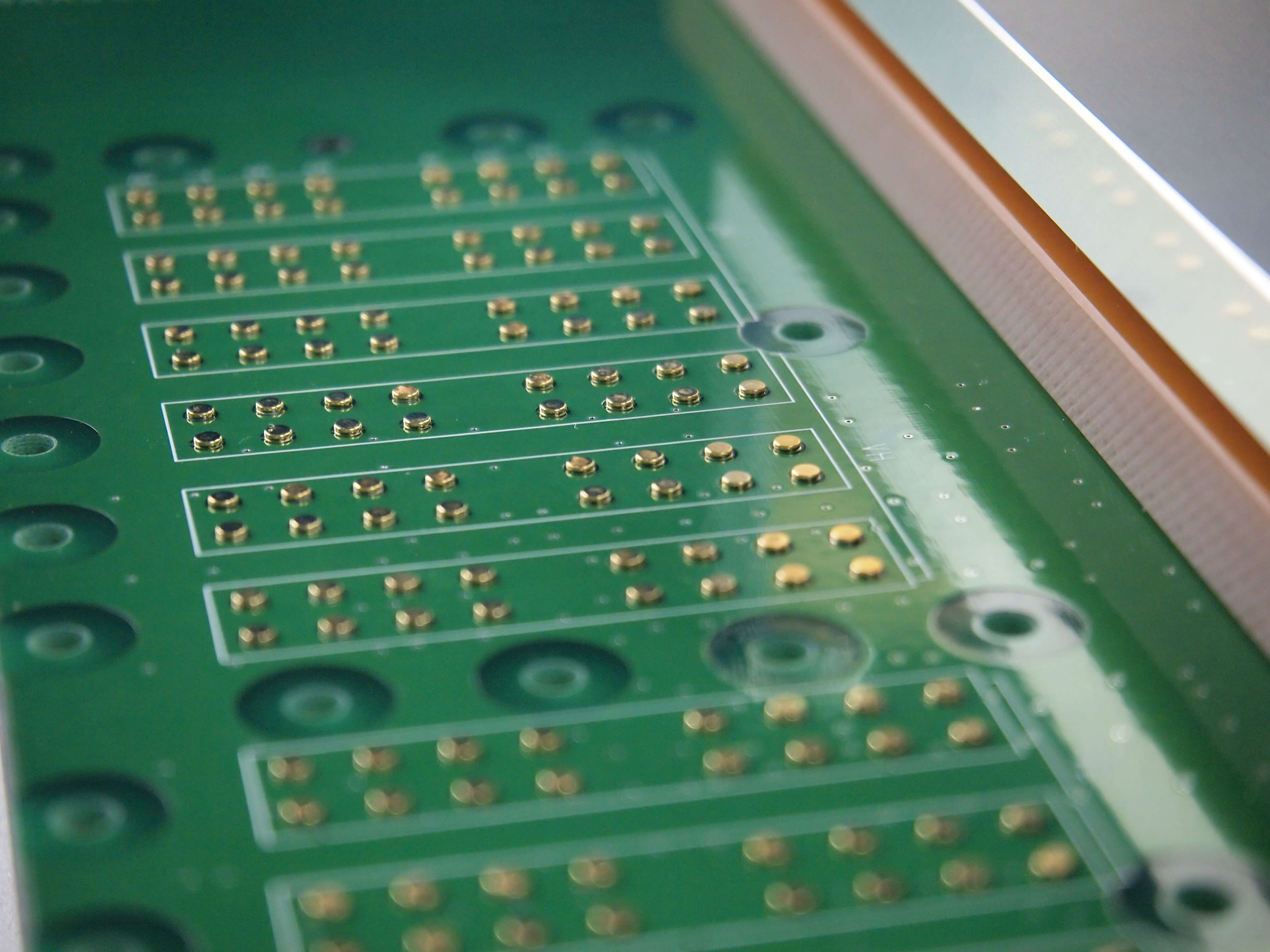
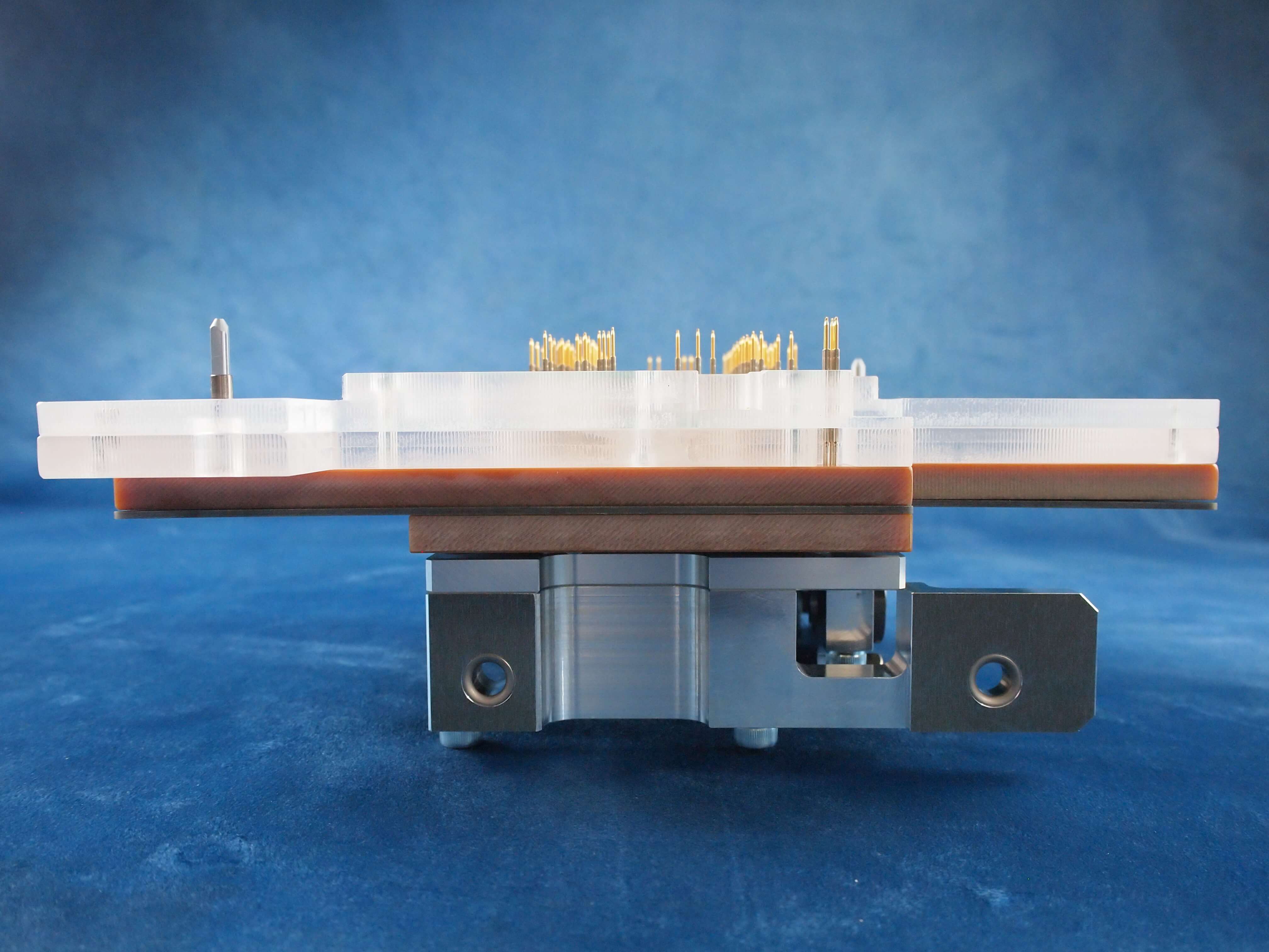
Allows for electrical and visual test*
* Makes it possible to electrically check the polarity of aluminum electrolytic capacitors, the number of connector poles, and the orientation of mounted components, which required visual checking with conventional methods. Note, however, that this is only possible if the connector shape can be determined.
Allowable probing pad diameter: 0.8 mm minimum.
Connector and jig sizes to suit various inspection machines, as well as manual operation test jigs using our hand press.
Electrical testing is performed on the electronic components after mounting to determine if the constants are matched.
Some parts may be outside the detection coverage due to the influence of parallel components or wraparound. Please contact us for details.
Specifications
Manufacturing example (Size and weight will vary depending on specifications.)
Product name
In-circuit test jig
Type
ICT (PCB: printed circuit board)
Size
506 × 330 × 282 mm
Weight
600 g
Applications
Inspections of electronic component constants and component presence on mounted boards

In addition to checking electronic component constants on mounted boards, the polarity and orientation of connectors can also be checked.
Strain measurement of the board is also available as an option.
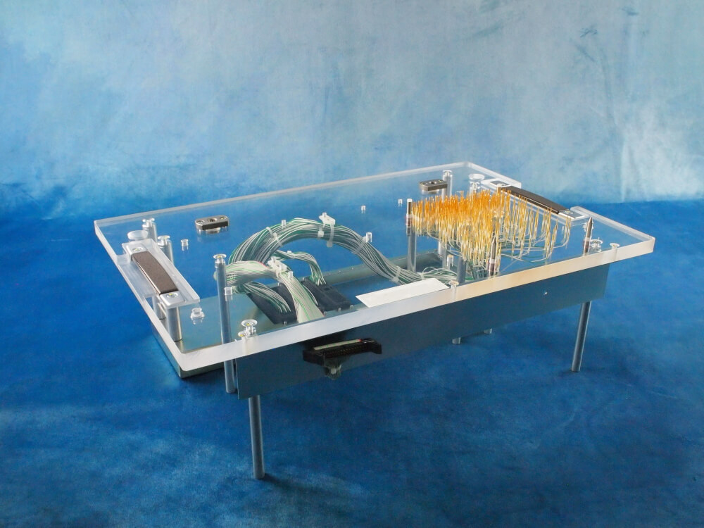
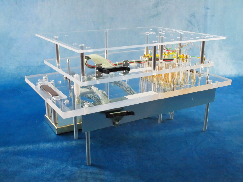
Bottom jig side: Antistatic acrylic is also available in addition to normal acrylic.
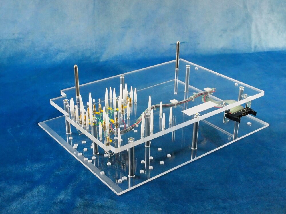
Top jig side: Component presence inspection is performed by using switch probes.
(The image above shows the jig inverted, with the inspection part on top.)
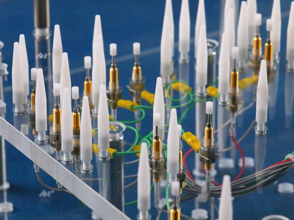
Enlarged view of top jig side:
Switch probes to match the detection height of each connector.
The switch probe is the brass-colored part.
(The image above shows the jig inverted, with the inspection part on top.)
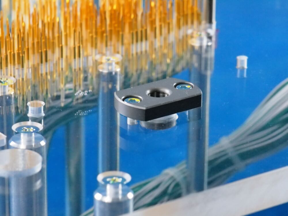
In addition to checking electronic component constants on mounted boards, the number of poles and orientation of connectors can also be checked.
Strain measurement of the board is also available as an option.
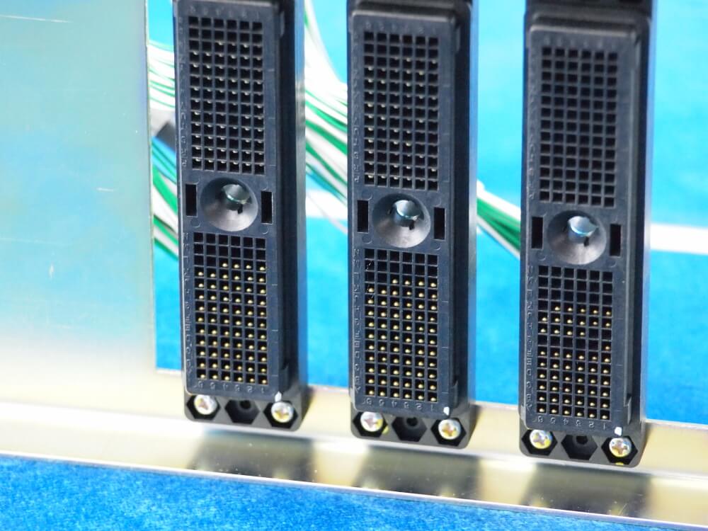
We select connectors to match the specifications of each inspection machine.


